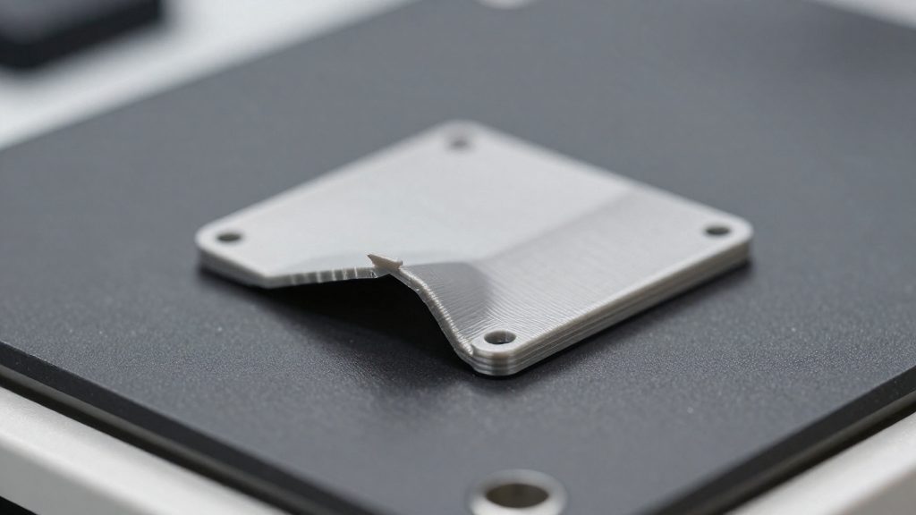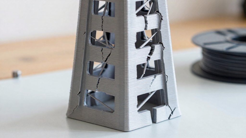
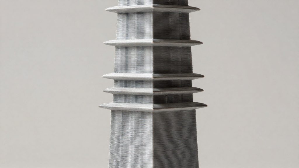
Each lost step moves the nozzle slightly out of position, and every later layer is printed from that shifted position. On a short part the offset may stay within tolerance, but on a tall part it accumulates over many more layers until it shows as a visible step in the walls.
Why do layer shifts show up on tall prints?
Open-loop steppers cannot recover a lost step
Stepper motors move in fixed increments, and the firmware assumes each commanded step was executed. Snapmaker’s documentation notes that FDM printers are open-loop, so lost steps are never corrected. The printer’s internal position count and the physical position of the nozzle then drift apart without any warning.
Errors carry through every later layer
After a step is lost, the error is not reset at the next layer. Each subsequent layer is positioned relative to the offset, so the shift is inherited upward rather than corrected. The result is a clean vertical boundary where the upper part of the model sits displaced from the lower part.
Tall prints give shifts more height to accumulate
A tall print has more layers, so it offers more opportunities for a step to be lost and more height over which an offset can build. A shift of a few tenths of a millimetre may be invisible on a short part but clearly visible on a tall one. Lowering motion demands can reduce the chance of lost steps.
Check belts, pulleys and set screws
Loose mechanical parts in the X and Y drive are a direct cause of skipped steps. A stepper motor moves a fixed amount per step, but if a belt slips on its pulley or a motor pulley turns on its shaft, the carriage ends up somewhere other than where the firmware sent it. This is why a mechanical slip on a tall print typically appears as a step in the walls, and repeated slips can add further steps higher up.
Tighten and inspect the X and Y belts
Pluck each belt and listen. Creality advises tightening the X and Y belts until they give a low tone when plucked. Then inspect the full length of each belt for fraying, cracked teeth or worn edges. Frayed belts should be replaced, not just retensioned, because damaged teeth can slip on the pulley even when the tension is correct.
Seat the motor pulleys and grub screws
Loose grub screws on stepper shafts can cause skipped steps. On each motor pulley, confirm the pulley is firmly attached and that its set screw sits on the flat of the motor shaft. A set screw resting on the round part of the shaft has little grip, so the pulley can rotate independently of the motor. Re-check both X and Y pulleys, since a pulley that is loose on one axis can look fine on the other.
Check for binding by hand
With the motors off, move each axis by hand along its full travel and feel for binding. A spot that catches or requires force points to a mechanical obstruction. Snapmaker recommends cleaning and lubricating the linear modules after this check. Retest the axes by hand once the modules move freely.
| Check | What to look for | Action |
|---|---|---|
| X and Y belt tension | Dull or loose tone when plucked | Tighten until the tone is low |
| Belt condition | Fraying along the belt | Replace the belt |
Is your stepper driver overheating?
Layer shifts that appear partway through a long print can come from the electronics rather than the mechanics. According to Creality, hot stepper drivers and motors lose torque on long prints, so a motor may stop delivering enough force to move an axis accurately even when nothing is physically wrong. The effect builds with print duration, which is why tall and long jobs are the ones most likely to show it.
Driver temperature is the first thing to check. After a long run, power the printer off and unplug it. Check the stepper driver chips on the control board and the motor casings with a non-contact thermometer, or let them cool before touching them. Compare them with the same parts after a short test print. If the driver or motor is clearly hotter after the long job, heat may be contributing, but this single check is not proof, and a normal temperature does not rule heat out. Let the parts cool before touching them, or use a non-contact thermometer, because they can cause burns.
Next, improve airflow around the control board:
- Make sure the board’s vents are not blocked by cables, spools or debris.
- Add a fan that moves air over the electronics, or clean the existing one.
- Confirm the fan spins freely before assuming it is working.
Lowering motor current is the second step, and it requires care. Reduce the current slightly, in small increments, and only as the manual for your board describes. Motor current (often set through VREF) is an advanced adjustment, and wrong values can damage components. If the manual does not cover your board clearly, consult official support before changing anything. Write down the original value first so you can restore it, then repeat the long print to see whether the shifts have stopped.
Rule out nozzle collisions
A nozzle collision happens when the nozzle or its carriage strikes material that has already been printed. According to Creality, collisions with curled edges or blobs are more common on tall or complex models, where the nozzle travels close to earlier layers and overhangs. Start by checking whether the geometry places the nozzle near finished walls at the height where the shift occurred.
Curled edges and blobs are associated with collisions, but they are not proof of one. Curling and blobbing can also come from material and temperature settings, so the defect alone cannot identify the cause. The signal becomes more useful when the defect sits where the nozzle would have passed close to a finished wall, not just at the height where the layers moved. Compare the location of the marks with the model’s outline and any protrusions.
The absence of curled edges and blobs does not exclude a collision. The nozzle can knock a thin wall or a bridge without leaving a visible mark, and the shifted layers may be the only evidence. A clean surface should not be treated as a clearance check.
To test the collision hypothesis:
- Inspect the part at the height where the layers changed, looking for scraped edges, lifted corners or nicked walls.
- Identify the tallest features and overhangs, since these are the areas where the nozzle is most likely to meet earlier material.
- If a collision is suspected, Snapmaker suggests raising Z-hop from 0.5 mm to 1 mm, then reprinting to see whether the shift repeats.
Slow down speed, acceleration and jerk
Aggressive motion settings are one of the first things to back off when a tall print shifts. Every move the firmware requests is a load the stepper motors must follow, and on a tall part the cumulative effect of a motor struggling to keep up can show up as an offset. According to Creality, the safest approach is to start from conservative values and adjust them in small steps.
| Setting | Creality starting value |
|---|---|
| Print speed | 40-50 mm/s |
| Acceleration | 500-1000 mm/s² |
| Jerk | 5-10 mm/s |
A single overloaded move at one height offsets everything printed after it, so a conservative baseline is a useful first test.
Building a custom profile
When you create a custom profile, reduce print speed, travel speed, jerk and acceleration together rather than changing one value alone. Snapmaker recommends a starting reduction of 20-50% for each of these values. Choose a reduction within that range, print the tall model again, and check whether the shift has moved or disappeared.
Adjust one step at a time and keep the changes small. If a value that was lowered by a large percentage causes unnecessarily long print times, move it back up gradually instead of reverting the whole profile at once. Travel speed deserves the same treatment as print speed, because long non-printing moves on a tall model add up to many accelerations and decelerations.
What if it always shifts at the same height?
If every print shifts at the same height, Creality advises suspecting the Z axis or a G-code glitch at that layer. A fixed-height shift points to something that catches or slips at one specific point of travel, rather than a general fault.
Mechanical causes on the Z axis
Creality lists four Z-axis faults to check: a bent leadscrew, debris on the threads, coupler slip, and binding. The table below covers the first three; for binding, move the axis by hand with the motors off and feel for a spot that catches. A bent leadscrew can bind as it turns through one part of its travel, and grit on the threads can catch the nut at the same height on every print. A coupler slip stops the platform moving as commanded, and binding is any point where the carriage or rail resists movement.
The shift you see is the height where the error started, and everything above it is offset.
Checking each suspect
| Suspect | What to check |
|---|---|
| Bent leadscrew | Turn the leadscrew by hand with the motors off and feel for a tight spot at one height |
| Debris on threads | Clean the threads |
| Coupler slip | Confirm the coupler is tight on both the motor shaft and the leadscrew |
G-code glitch at the affected layer
If the mechanics move freely, the fault may sit in the G-code. Creality names a glitch at the affected layer as the alternative cause, so open the sliced file and inspect the layer where the shift begins. Snapmaker warns that adjusting motor current (VREF) is an advanced step to take only after consulting official support, because wrong settings can damage components.
Final checks before a long print
A tall print can run for many hours, so a profile error can waste the whole job. Before you start, confirm that your revised settings are saved in the profile the slicer uses to generate G-code. These edits only take effect if the saved profile carries them into the sliced file.
Confirm the profile is saved and selected
- Reopen the profile editor and check that each revised speed field shows the new value. An unsaved edit leaves the old values in place.
- Check that the profile name in the slicer’s profile selector matches the one you edited. Selecting the original profile by mistake sends the old speeds to the printer.
- Save the revised version under a distinct name and leave the original untouched, so you can roll back if the new values cause problems.
- Check the Z-hop field in the same pass. It is stored in the same profile as the speed fields.
Verify the values in the sliced G-code
Saving the profile does not prove the G-code matches it, so slice the model and inspect the output. Open the exported file and find the feed rate (F) words that set speed. In G-code, F values are expressed in mm/min, so multiply your target speed in mm/s by 60 before comparing. Check travel moves separately, because they use their own speed setting rather than the print speed.
Frequently asked questions
Why does the layer shift appear at the same height on every print?
If every print shifts at the same height, the likely causes are a Z-axis fault (a bent leadscrew, debris on the threads, coupler slip or binding) or a G-code glitch at that layer. Check the Z axis first, because a fault there affects every print in the same way.
Can a hot stepper driver really cause a layer shift?
Creality notes that stepper drivers and motors that overheat lose torque on long prints, which can make them skip steps. Improving airflow around the control board and cleaning or adding fans can help, but a warm driver is only a hint, not proof of the cause. Adjust motor current only as the manual describes, and only slightly.
Does a curled edge or blob prove the nozzle hit the print?
No. Curled edges and blobs are associated with a nozzle collision on tall or complex models, but they do not confirm one, and their absence does not rule one out. Look at the surrounding layers and the height where the defect starts before you decide on a mechanical fix.