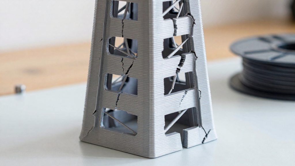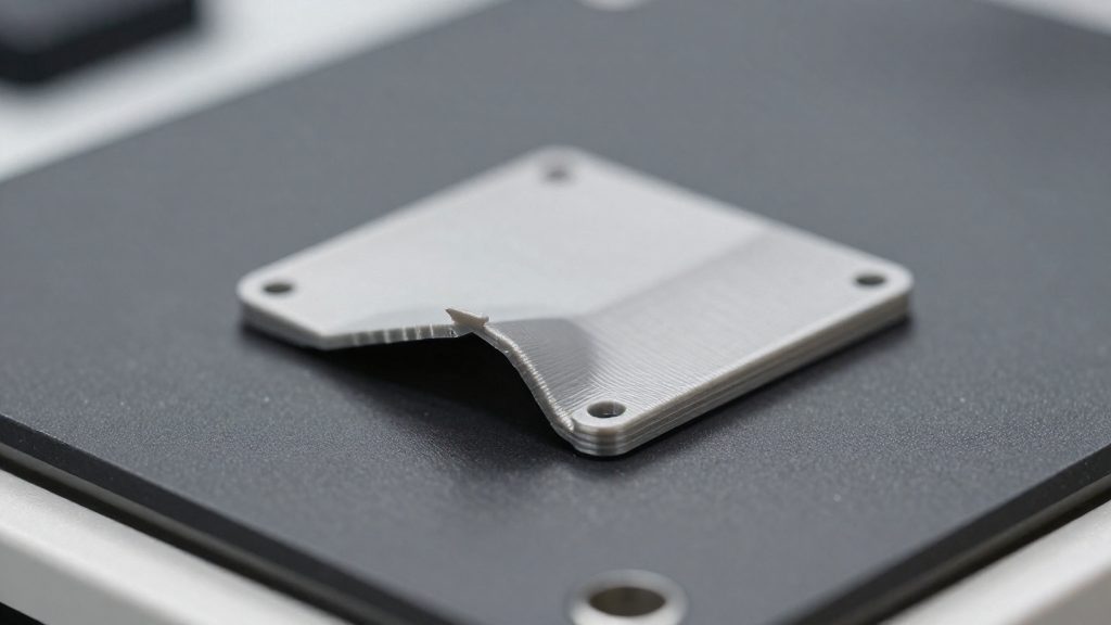
Corner lift, also called warping, happens because the plastic shrinks as it cools, and the shrinkage is uneven across the part. According to Snapmaker (2026), lower layers cool and shrink while upper layers are still warm, and the resulting internal stress lifts the print, especially at the corners. The mechanism is thermal contraction, and it explains why corners lift before the rest of the part.
Why do 3D print corners lift?
Lower layers cool and shrink first
Each layer is extruded molten and solidifies as it cools. The layers printed first have already cooled and contracted by the time the part is taller, so the base of the part is the first region to shrink. The base is also bonded to the build plate, so it cannot contract freely in every direction.
Warm upper layers hold tension
The layers printed most recently are still warm when the lower ones contract. The contraction of the cooled base therefore works against the warm layers above it, and tension builds between the two zones. This tension is the internal stress that pulls the print away from the bed.
Stress concentrates at corners and edges
The internal stress is not evenly distributed across the footprint. It is strongest at corners and edges, which is why the corners lift first and most visibly (Snapmaker, 2026). This is why the corners lift first and most visibly, and why the lift can start at the perimeter of a flat part before the center moves.
How do I stop warping on the first layer?
The first layer is the only part of the print bonded to the bed, so its contact with the plate is the first thing to control.
Calibrate nozzle height and squish
Squish is how far the first extruded line is flattened against the bed. A nozzle set too high leaves round, weakly bonded lines. A nozzle set too low drags material across the plate and can clog. Adjust the Z offset in small steps and print a single-layer test square. The lines should merge into one smooth, continuous surface with no visible gaps between them. Repeat this check whenever the bed, build plate or nozzle is changed, because the nozzle height relative to the plate changes with them.
Prepare the bed surface
Clean the build surface before each print. Fingerprint oil and dust reduce bed adhesion, so wipe the plate with a clean cloth and a degreasing solvent, then handle it only by its edges.
Slow the first layer
Printing the first layer more slowly gives the extruded plastic more time to bond with the bed before the next layer is laid. Set a reduced first-layer speed in the slicer and keep it separate from the speed used for the rest of the print, so the upper layers stay fast. The right value depends on the material and printer.
Brim, mouse ears and rafts
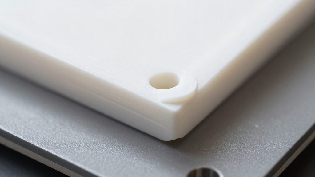
Three anchoring options work from the bed side: a brim, mouse ears and a raft. They differ in how much material they add, how much of the first layer they cover and how they are removed. The right choice depends on the footprint of the part and how prone the material is to warping.
Brim
A brim is a band of extra material printed around the outline of the first layer and connected to the part. According to QIDI Tech (2026), a brim of 5–10 mm of extra first-layer width is a recommended fix for corner lift. The wider contact area helps resist the pull at the corners. Snapmaker (2026) notes that brims suit parts with a large flat base.
Mouse ears
Mouse ears are small discs placed only at the corners of the first layer. They add anchoring where lift usually begins, using far less material than a full brim. In the slicer, add them at each corner, then remove them by hand after printing.
Raft
A raft is a thick, sacrificial base printed under the entire part and separating it from the build plate. Snapmaker (2026) states that rafts suit complex geometries or warp-prone materials. Because the raft covers the whole footprint, it works where a brim cannot reach every contact point of an irregular base.
| Option | Best suited to | Where it adds material |
|---|---|---|
| Brim | Parts with a large flat base | Outline of the first layer |
| Mouse ears | Small corner anchoring | Discs at the corners only |
| Raft | Complex shapes and warp-prone materials | Whole footprint, under the part |
What bed temperature and fan settings prevent warping?
Bed temperature and part fan speed work together. A warm bed slows how fast the base layers cool and contract, and the part fan controls how quickly each new layer solidifies. QIDI Tech (2026) gives material-specific starting values for both.
| Material | Bed temperature | Part fan |
|---|---|---|
| PLA | 50–60 °C | 50–100% |
| PETG | 70–85 °C | 30–50% |
| ABS | 90–110 °C | 0%, except on bridges |
Part fan settings by material
The part fan has the widest range for PLA, which tolerates strong cooling. PETG needs a lower setting, at 30–50%, because it is more sensitive to rapid cooling. ABS is the exception: QIDI Tech (2026) suggests keeping the fan off.
The ABS bridging exception
The ABS bridging exception is the only case where ABS gets fan airflow. Bridges are unsupported horizontal spans, and they cool poorly without it. Set the bridge fan speed within your slicer’s bridge settings and check the result on a test part.
Delayed fan start and bed boost
Creality (2026) recommends delaying the part fan until after the first few layers, so the base layers stay warm and bonded to the bed. The same source states that raising the bed temperature by 5–10 °C can improve adhesion. Use this bed boost as a targeted adjustment within the material range above, rather than as a replacement for it.
Do I need an enclosure for warping?
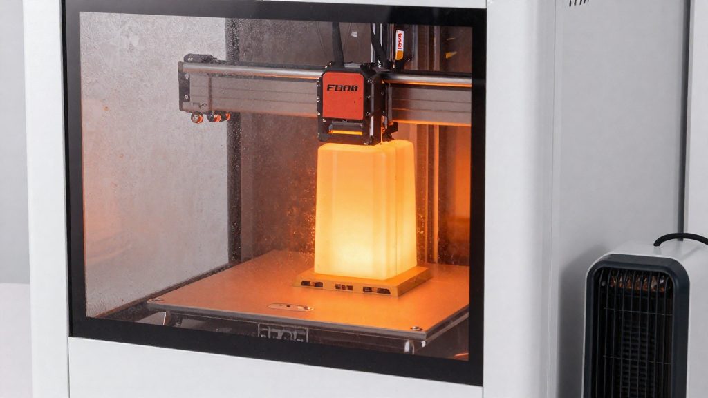
An enclosure works on the cooling side of warping. According to Creality (2026), enclosing the printer keeps temperatures uniform and blocks drafts, so the layers cool more evenly instead of one side losing heat faster than the other.
Whether you need one depends on the material. For PLA, the main requirement is the room rather than a cabinet. Print in a room at about 20–25 °C, away from open windows and air-conditioning vents (Snapmaker, 2026). The goal is to remove cold air moving across one side of the bed.
For ABS, the enclosure should become a heated chamber. QIDI Tech (2026) states that a heated chamber is strongly recommended for ABS. Without one, the air around the part stays cold, and the temperature difference between the lower and upper layers is what drives the lift.
If you print PLA without an enclosure, the practical steps are:
- Move the printer away from windows, doors, and vents.
- Keep the room within the 20–25 °C range.
- Stop drafts from reaching the bed, for example by placing a cardboard shield around the printer if the room is hard to control.
Design changes that reduce corner lift
Geometry edits work on the same mechanism that causes warping. Changing the model before slicing reduces how concentrated that stress is at the corners and how much of the first layer is bonded to the plate.
Rounding sharp corners in the CAD model
A 90-degree corner concentrates stress at a single point, so the first lifted edge often starts there. In your CAD software, replace sharp vertical edges with a fillet (a rounded edge) or a chamfer (an angled cut). The radius should be large enough that the outline changes direction gradually. Apply the rounding to the outer corners of the base, since that is where the lift starts. Then check the slicer preview to confirm the rounded outline still matches the functional shape of the part and does not thin any walls.
Reducing the contact footprint
The contact footprint is the area of the first layer that touches the build plate. A wide, solid base bonds a large first layer, and the shrinkage of that layer pulls against the plate along its whole edge. To reduce it, hollow out large flat bases, split a wide plate into smaller sections where the design allows, or remove non-functional flat areas. Keep the walls thick enough to hold the layer lines together, and avoid cutting so much that the part loses its ability to stay on the bed.
Orienting wide, flat bases
Orientation determines which faces touch the bed. Rotating a flat plate onto its edge shortens the bonded base, but it makes the part taller and can introduce overhangs that need supports. Choose an orientation that shortens the base without adding significant height, and confirm that the new overhangs are acceptable before slicing.
What shrinkage data exists for ABS, PLA and PETG?
Shrinkage is the main measurable reason one material warps more than another. Among the three materials compared here, ABS is the only one with a published shrinkage figure: QIDI Tech (2026) states that ABS shrinks about 1–2%, which is 2–4 mm of contraction on a 200 mm part. That contraction is what pulls the corners of a large ABS print away from the bed.
The mechanism is the same for every material. The more a material contracts as it cools, the more stress builds up across the part.
The ranking below uses only the figures the consulted sources provide.
| Material | Shrinkage data in consulted sources | Warping tendency |
|---|---|---|
| ABS | About 1–2%, or 2–4 mm on a 200 mm part | Significant shrinkage; no comparison with PLA or PETG is possible from the consulted sources |
| PLA | No shrinkage figure given | Not ranked; sources recommend a room at 20–25 °C, away from open windows and air-conditioning vents |
| PETG | No shrinkage figure given | Not ranked; the consulted sources do not specify its shrinkage |
PLA and PETG cannot be placed on the same numerical scale as ABS, so the table orders them by data availability, not by measured warping.
The 2–4 mm figure matters most on tall parts. Because shrinkage is a percentage of part size, a 200 mm part contracts ten times more in absolute terms than a 20 mm part of the same material.
Quick troubleshooting checklist
Corner lift can come from two different causes, and the height at which it starts tells you which one applies. According to QIDI Tech (2026), corners that lift within the first 10–20 layers usually point to bed adhesion or bed temperature, while lift that appears only once the print is tall usually points to accumulated shrinkage and cold ambient air. Identify the timing first, then change one variable at a time.
Lift within the first 10–20 layers
Check the bed temperature against the filament before changing anything else. Use the material row in the table below as your starting point and stay within its range. If the corners still lift, raise the bed temperature in small steps.
Lift on tall prints
When lift appears only on taller parts, the likely cause is accumulated shrinkage over the height of the print. Lower layers cool and contract while upper layers are still warm, so the stress grows as the part gets taller. Cold ambient air contributes to the same symptom, so reduce cold air reaching the upper part of the print.
Bed and fan settings by material
| Material | Bed temperature | Part fan |
|---|---|---|
| PLA | 50–60 °C | 50–100% |
| PETG | 70–85 °C | 30–50% |
| ABS | 90–110 °C | 0% except on bridges |
Symptom-to-fix reference
| Symptom | Likely cause | First fix |
|---|---|---|
| Corners lift within the first 10–20 layers | Bed adhesion or bed temperature | Set the bed to the material range, then raise it in small steps (Creality suggests 5–10 °C can improve adhesion), staying within the material’s range where possible |
| Corners lift only on tall prints | Accumulated shrinkage over height | Keep the part fan within the material range and reduce cold air at the upper layers |
Frequently asked questions
Why does my print lift only after it gets taller?
Lifting that appears only once the print is tall usually points to accumulated shrinkage combined with cold ambient air, rather than to the first layer. Enclosing the printer keeps temperatures uniform and blocks drafts, which limits how much the upper layers cool.
Is a brim enough to stop corner lift on ABS?
A brim adds 5–10 mm of extra first-layer width, which gives the corners more bonded area to hold onto. ABS shrinks about 1–2%, which is 2–4 mm on a 200 mm part, so a brim helps but a heated chamber is strongly recommended for ABS by QIDI Tech (2026).
Should I raise the bed temperature or the part fan speed first?
If corners lift within the first 10–20 layers, check bed adhesion and bed temperature first, since that pattern points to the first layers. Raising the bed temperature by 5–10 °C can improve adhesion, and QIDI Tech (2026) suggests keeping the part fan low for ABS (0%, except on bridges).