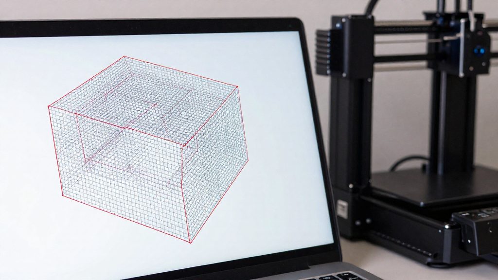
Non-manifold geometry in an STL file is a mesh that breaks the closed-shell rule, most typically because at least one edge is shared by more than two faces (holes in the mesh also make a model non-manifold), so the surface no longer describes one clean, closed solid. Non-manifold geometry in an STL file is a mesh that does not describe one clean, closed solid. The typical case is an edge shared by more than two faces, but holes in the mesh also make a model non-manifold. A valid mesh is a closed shell in which every edge joins exactly two faces, which lets the slicer tell inside from outside. When an edge breaks that rule, the model’s intended shape becomes ambiguous.
What does non-manifold mean in an STL file?
A non-manifold edge is an edge where more than two faces meet. According to Hubs (Protolabs Network, 2026), the typical causes are an extra internal surface or one edge shared by several separate bodies.
Edges shared by more than two faces
When a third face meets an edge that already connects two faces, the mesh no longer shows which faces bound the solid’s interior. The edge then has no single, unambiguous boundary. This is the defining condition: the count of faces per edge, not the visible shape, decides whether a model is manifold. A model can look correct in a viewer and still contain such edges, because the extra faces may sit hidden inside or along the surface.
Extra internal surfaces and separate bodies
Two common sources produce this condition. An extra internal surface is leftover geometry inside the solid, often created when a part is modified without merging the old body. Separate bodies sharing an edge occur when two parts touch along a line instead of being fused into one volume. In both cases the mesh has more faces meeting at a shared edge than a closed shell allows, so the file no longer represents one watertight object.
What a manifold shell means for printing
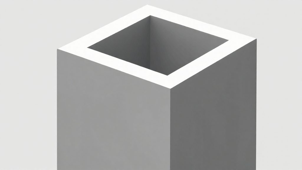
According to DigiKey Maker.io (2026), a manifold shell can hold water in theory, meaning it encloses a volume with no gaps in its boundary. Manifold status is therefore the baseline for a solid, printable mesh. It is not a full guarantee of correct slicing.
Why do non-manifold errors ruin prints?
According to Hubs (Protolabs Network, 2026) and DigiKey Maker.io (2026), According to Hubs (Protolabs Network, 2026), non-manifold edges rarely cause major slicing failures. Their main effect is unpredictable output, because the intended geometry becomes unclear to the slicer.
The main causes and their effects on slicing are:
| Cause | Effect on slicing |
|---|---|
| Extra internal surface | An edge is shared by more than two faces, so the slicer cannot tell which surfaces define the solid |
| Edge shared by separate bodies | The boundary between bodies is ambiguous, so the solid’s outline is uncertain |
| Hole in the model | The model becomes non-manifold, and Cura can slice it incorrectly |
According to DigiKey Maker.io (2026), holes make a model non-manifold, which can make Cura slice it incorrectly. A manifold shell can hold water in theory, and a hole breaks that closed condition.
How to spot non-manifold edges in your slicer
In Slic3r, the Manifold indicator at the bottom right shows the status of the loaded STL, so you can check a model before going further.
Reading the Manifold indicator
The Manifold indicator sits at the bottom right of the Slic3r window. Read it right after loading the file:
- Load the STL into Slic3r.
- Look at the bottom-right corner of the window.
- Compare the reading with the table below.
| Indicator reading | What it means | Next step |
|---|---|---|
| Manifold: Yes | The mesh passes the manifold check | Continue to slicing |
| Manifold: No | Non-manifold edges are present | Repair the file before slicing |
Identifying models that need repair
A model that returns “Manifold: No” usually has one of two patterns:
- Internal surfaces left over from a boolean operation or a merged assembly, which create extra faces inside the solid.
- Separate bodies that touch along one shared edge rather than being fused into a single solid.
To narrow down the cause, look at where the problem sits in the model. The indicator alone does not tell you which of these patterns is present, and a single export can contain both.
The indicator only reports a status and does not tell you which edge is the problem; tools such as Meshmixer’s Inspector can help with repair.
Quick auto-repair with free tools
Automatic repair is the fastest first pass on an STL with non-manifold edges. The tools below can run a repair pass without any CAD work.
Slic3r: File > Repair STL file
Slic3r has a built-in repair command. The workflow is:
- Load the STL into Slic3r.
- Choose File > Repair STL file…
- Re-add the repaired file.
DigiKey Maker.io (2026) describes this repair as “far from perfect”.
Netfabb, Meshmixer and 3D Builder
Hubs (Protolabs Network, 2026) lists the following as general STL repair options:
- Netfabb: use its Repair command.
- Meshmixer: use its Inspector.
- 3D Builder: available as a general repair option. The sources do not specify a particular command.
- Free online repair tools: the same source lists these as an option, without naming a specific service.
Export the repaired model, then re-import it into the slicer.
Fixing the model in CAD or Blender
Hubs recommends fixing the CAD model rather than patching the STL, so the most reliable fix is to correct the design where it was created. Hubs (Protolabs Network, 2026) recommends fixing the CAD model rather than patching the STL.
When to return to the CAD source
Go back to the original design file when the error comes from the model’s construction. Look for internal faces left from a boolean operation or a combined part, and for two bodies that touch only along one edge. Correct the geometry in the CAD program, then export a new STL. This keeps the design intent intact and avoids carrying a patched mesh into later revisions.
When Blender is needed
Modeling software such as Blender is needed in two documented cases:
- Reversed normals. This is where Blender applies.
- Files that need redesign. Some files need rework in modeling software such as Blender, since an automatic repair cannot restructure the geometry.
In modeling software such as Blender, the general approach is to import the STL, correct the faulty geometry and face orientation, and re-export the file for slicing.
| Symptom | Likely cause | Where to fix |
|---|---|---|
| Edge shared by more than two faces | Extra internal surface | Source CAD model |
| Edge shared by several separate bodies | Bodies joined at one edge | Source CAD model |
| Manifold model that slices incorrectly | Reversed normals | Modeling software such as Blender |
| Geometry needs restructuring | Model construction | Redesign in Blender |
Is it safe to auto-repair my mesh?
Automatic repair is a useful first pass, but it does not guarantee a correct print. According to DigiKey Maker.io (2026), the Slic3r repair command is “far from perfect”, and some files need to be redesigned in modeling software. The repair works only from the mesh itself, so it cannot tell which surfaces the designer meant to keep.
What a repair can and cannot fix
Automatic repair works from the mesh alone, so it may close holes but cannot tell which surfaces the designer meant to keep; files that need restructuring must be redesigned in modeling software.
Checking the repaired result
- In Slic3r, reload the repaired file and confirm that the Manifold indicator at the bottom right reads ‘Manifold: Yes’.
- Open the slicer preview and compare it with the original model. Look for filled openings, missing thin walls and surfaces that have merged.
- Check any area where the repair closed a gap, since that is where the mesh was changed most.
A manifold model can still slice wrongly
A ‘Manifold: Yes’ result shows that the mesh is closed. It does not guarantee a correct slice. DigiKey Maker.io notes that if a model is manifold but still slices wrongly, reversed normals are a likely cause, and fixing them requires modeling software. So a passing indicator is a necessary check, not a final verdict.
When to fix the source instead
Auto-repair is most reasonable for files you cannot edit at the source, and its output should be treated as a draft until the preview confirms the geometry.
Preventing mesh errors before export
Most non-manifold problems are cheaper to prevent in the design than to repair afterwards. Two design rules address most of the risk before the file is exported.
Add thickness to thin sections
Hubs recommends adding thickness to thin sections in the CAD model before exporting.
- Set the thickness in the CAD tool, not by editing the STL after export.
- Re-check thin features after any operation that changes wall thickness.
Leave clearance between unconnected features
When two features should not connect, do not let them touch or overlap. Hubs gives 0.3 mm as a clearance that is usually enough.
Frequently asked questions
Should I repair the STL file or fix the original model?
Fix the original model in your CAD software whenever you can, because a repaired STL still carries the underlying design problem. Repair tools such as Netfabb, Meshmixer, 3D Builder, or Slic3r’s File > Repair STL file can close holes and clean up the mesh quickly, but Slic3r’s own repair is described as far from perfect.
My model shows “Manifold: Yes” in Slic3r but still slices incorrectly. What should I check?
Check the face normals, which point each triangle inward or outward. Reversed normals are a likely cause of incorrect slicing even when the manifold check passes, and correcting them requires modeling software such as Blender.
Will non-manifold edges always ruin my print?
No. Non-manifold edges rarely cause major slicing failures on their own, but they leave the intended geometry unclear, so the slicer’s result can be unpredictable. Inspect the sliced preview before printing to confirm that walls, infill, and thin features look as you expect.