Why print orientation matters
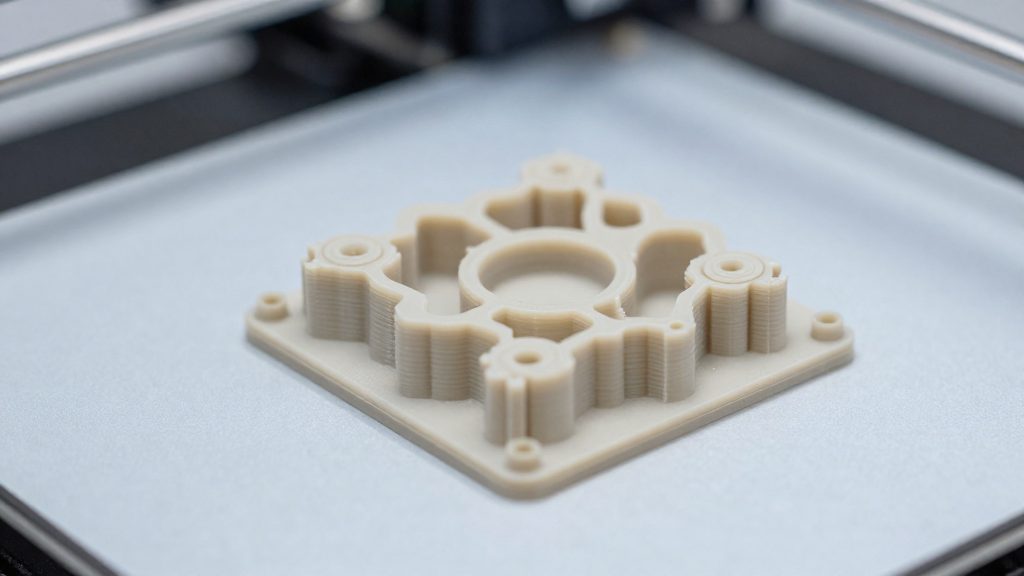
Orientation sets the layer count. A broad, flat footprint on the build plate needs fewer layers. Standing the same part upright on a narrow edge stacks more layers, so the job takes longer even though the geometry has not changed.
Orientation also controls surface quality. Layer lines appear on every face that is exposed to view, and Unionfab notes that orientation changes how visible those lines are. Faces that will be seen in use should therefore point in the direction that hides the lines best.
Print success depends on how the geometry sits relative to gravity.
For resin (SLA) printing, the priority shifts to the cross-section. Orienting the part to limit the cross-sectional area per layer reduces the stress applied during each peel, which lowers the risk of a failed layer.
How do I choose the best orientation for an STL file?
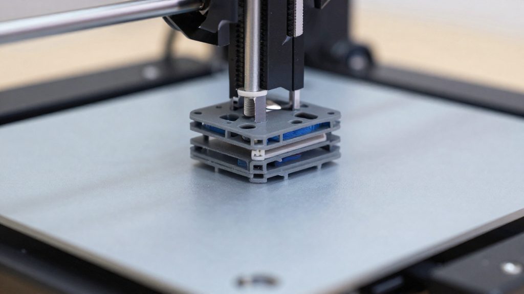
The best orientation gives the part a broad, stable base on the build plate while needing the least support material. These two goals often point the same way. According to Unionfab, an orientation that maximizes build-plate contact reduces the amount of support the print needs. Orientation selection is therefore a trade-off: rotate the model until the base is as large as practical, then check how much support the slicer will have to add under the overhangs.
Maximising build-plate contact for adhesion
A broad contact area with the bed improves adhesion. Racklify (2025) also notes that it lowers the layer count, which shortens build time. In your slicer, rotate the model and compare the footprint of each candidate position. The orientation that lays the largest flat face on the plate is usually the best starting point. A part resting on a narrow edge or a single corner has less area bonded to the plate, so its adhesion depends on a smaller footprint.
Minimising support material volume
Support volume is driven by downward-facing surfaces that have no material beneath them. Each candidate orientation should be checked for these surfaces. Large unsupported overhangs add a lot of support, while small features may need little or none. Compare the support estimate in the slicer for two or three positions before committing.
Placing the support contact points
The same rotation that moves support away from a face can change that face’s surface finish.
- Rotate to the largest stable flat base.
- Check which downward-facing surfaces need support.
- Accept a position with more base contact if it removes support from the visible side.
Overhangs and the 45° rule
An overhang is any part of the model that extends outward over empty space below it. On a fused deposition modelling (FDM) printer, the molten filament needs something to rest on while it cools, so the angle of each overhang decides whether the slicer has to generate support material.
According to Unionfab, angled overhangs exceeding about 45 degrees from vertical will likely need support material. Shallower overhangs can usually print unsupported. The measurement is taken from vertical, not from the build plate, so a surface that is almost upright is an easy print, while a surface close to flat underneath is the hard case.
Shallow overhangs and printing without support
The 45-degree figure is a guide, not a hard limit. Overhangs below it are usually held up by the layers beneath them, and the slicer leaves them unsupported. To check a model before slicing:
- Rotate the part in the slicer so that the most horizontal faces sit as close to vertical as the geometry allows.
- Look at the preview after slicing. Unsupported ledges show up as rough or drooping layers on the underside.
- Compare the overhang angle with the 45-degree threshold.
Steeper overhangs will likely need support, or a different orientation that reduces them. Reorienting the part can reduce or sometimes remove the need for support, so try it before accepting heavy supports.
Reducing overhangs on functional surfaces
Orientation affects the surfaces that matter most, not just the number of supports. According to Racklify (2025), where possible, keep critical faces away from supports to limit post-processing. For FDM, orient the part to reduce overhangs on functional surfaces.
Orientation and part strength
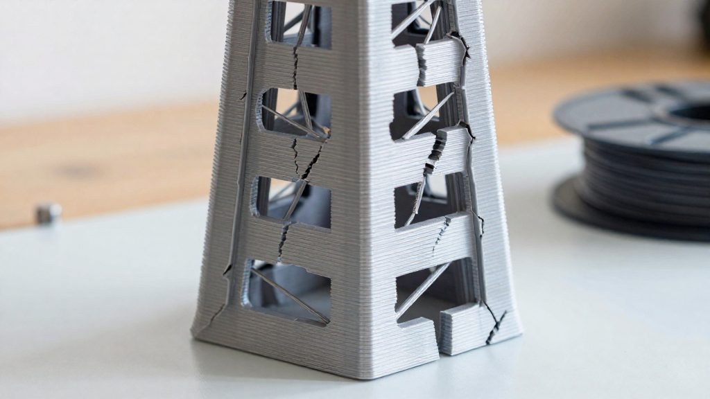
Layer direction affects how strong a printed part is. Unionfab’s guidance is direct: to improve strength, align continuous print layers along the main load direction. A continuous layer carries force along its full length without interruption, so the part holds up best when the force runs along the layers rather than across them.
Identifying the dominant load direction
Before slicing, decide which way the part will be pulled, bent or pushed in use. A hook, bracket or clip usually has one clear load path, and that path is the direction to align with the layers.
- Note the load case: what the part holds, and where the force is applied.
- Mark the force direction on the model in your slicer or CAD view.
- Rotate the model so that force direction lies flat in the build plane, so the layers run along it.
- Check the orientation from the side view before starting the print.
| Load case | Orientation goal |
|---|---|
| Pulling along the long axis of a bar | Lay the bar flat so its layers run along its length |
| Bending a flat tab or arm | Orient the tab so the bending force runs along the layers, not across them |
| Force pulling the layers apart | Avoid an orientation where the force pulls perpendicular to the layers |
Orientation strongly influences part strength, alongside other print settings.
Orienting for resin printers
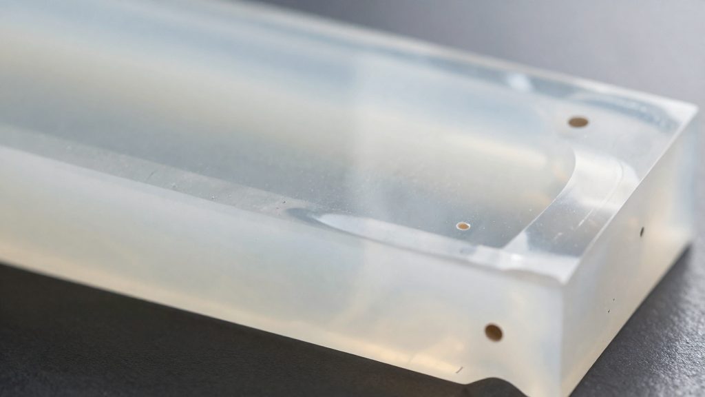
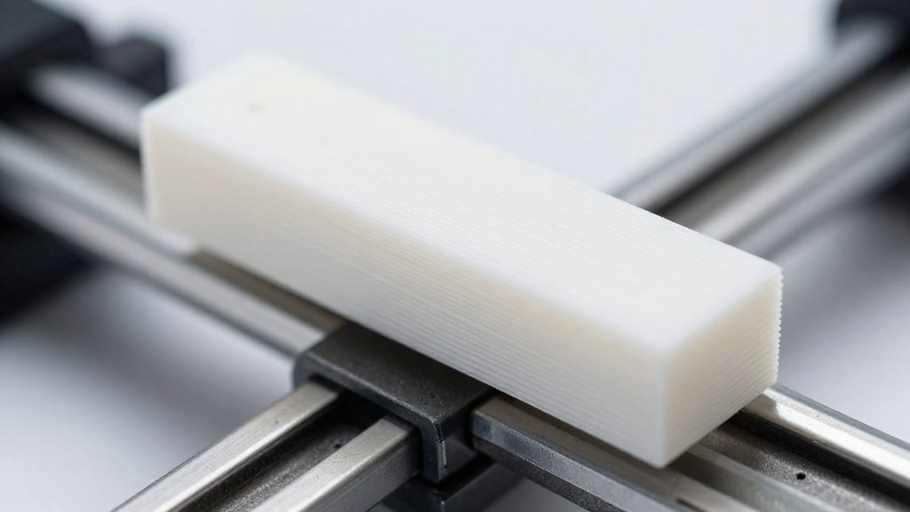
For a resin printer, the orientation question is less about overhangs and more about peel force. Each layer of a resin print is cured against the FEP film at the bottom of the vat, and when the build platform lifts, the film pulls on that cured layer. The larger the cross-sectional area of that layer, the more total force the film exerts on it. Orienting the part so that each layer covers as little area as possible is therefore one of the main ways to reduce the stress that can tear a print loose, warp it, or leave a failed layer behind.
Why cross-sectional area matters
The cross-sectional area is the footprint of the part at a given height, measured as a flat slice through the model. Peel stress scales with that footprint: a wide, flat part presents a large area to the film in a single layer, while a tall, narrow part presents a small area per layer. When you rotate the STL file in your slicer, you change which slice is the widest and how many layers share the largest footprint.
In practice, this means:
- Tilting a wide part so its broadest face is no longer parallel to the build plate spreads the large area across many thinner slices.
- Standing a tall, thin part upright keeps each layer small, so the peel force per layer stays low.
- Avoiding a single large flat face pointed straight down reduces the single worst-case layer.
Balancing peel stress against contact
Peel stress and build-plate adhesion pull in opposite directions. Limiting cross-sectional area per layer lowers peel stress on the film side. The practical goal is to find an orientation where the first layers still bond firmly to the build plate, while the per-layer footprint remains small enough that the film does not tear the part away during the lift cycle.
The choice of which face sits on the build plate is covered in the orientation-for-adhesion discussion, and support placement is covered separately.
Working through the orientation
- Load the STL into your slicer and identify the widest flat region of the model.
- Rotate the part so that this region is no longer a single flat layer facing the film.
- Check the layer-by-layer view and confirm that the largest cross-section is smaller than the original.
- Confirm that the bottom contact still gives the first layers a firm bond to the build plate.
Where should support contact points go?
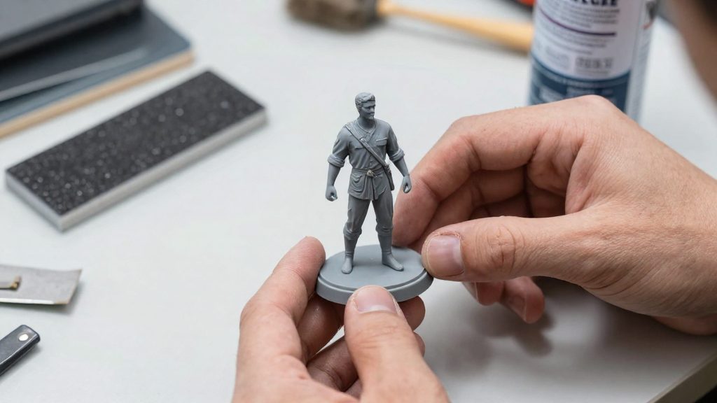
Support contact marks should land on the back or other low-visibility faces. Support remnants are easier to hide on the back of a part.
This section covers support contact points.
Placing support contact points
Work through these steps before slicing:
- Mark the critical faces. These are the visible surfaces, mating surfaces and functional surfaces that must print clean.
- Rotate the model so critical faces avoid overhangs. Overhangs on these faces are the ones most likely to need support, and support scars on them need post-processing to remove.
- Check where the supports would touch.
- Weigh base contact against support placement. Maximum build-plate contact reduces support, but if the best-contact position puts support on a critical face, compare it with other orientations in the preview.
Where these goals conflict, a shorter overhang on a critical face may be worth more than a support-free back. Compare the options in the slicer’s preview before committing to one.
Slicer tools for rotating and previewing
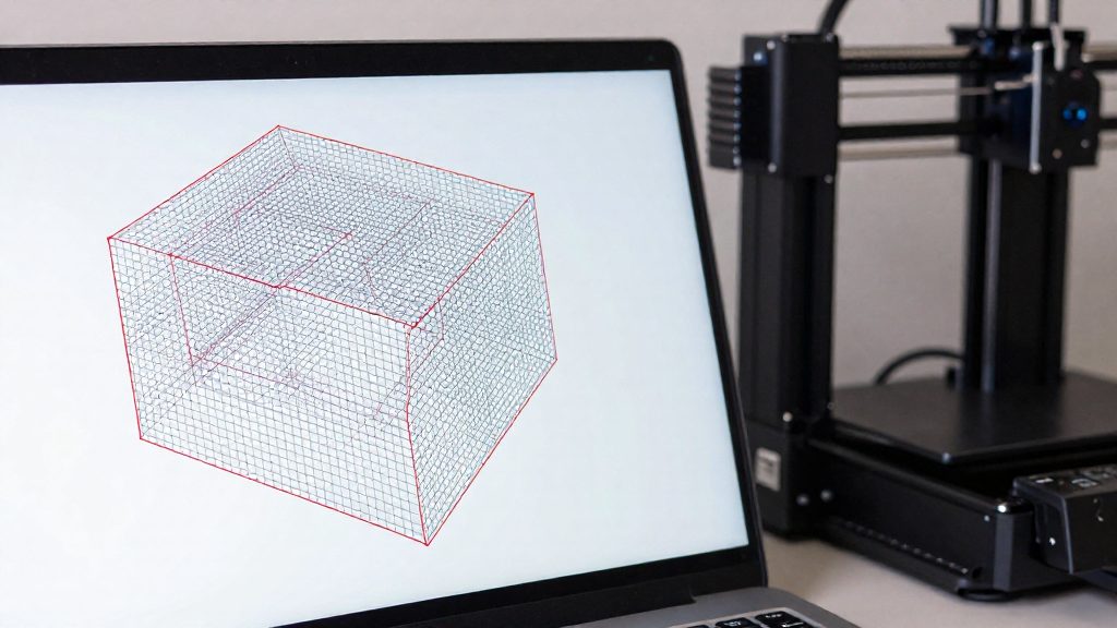
Most slicers let you test several orientations on screen before you send anything to the printer. The main tools are a rotate function, a lay-flat or place-on-face option, and a preview that shows the generated layers and any support material. Used together, they turn orientation from a guess into a comparison: rotate the part, check the preview, then slice and print.
Rotating to compare orientations
Rotate the model to each candidate position and check every one against the same criteria. Rotation changes three things at once: how much of the base touches the bed, how many downward-facing surfaces need support, and where layer lines fall on visible faces.
For each position, look at the following:
| Check in the slicer | What to look for | Why it matters |
|---|---|---|
| Bed contact | The largest flat footprint on the build plate | Better adhesion and fewer layers |
| Overhangs | Downward-facing surfaces highlighted in the preview | Surfaces that need support |
| Functional faces | Critical surfaces facing up or away from supports | Less post-processing |
| Load direction | Layer lines running along the main load | Better strength |
| Cross-section (resin) | Area of each layer | Lower stress during peel |
Rotation is also the quickest way to check the cross-section for resin printing. A position that limits the area of each layer reduces the peel forces the part experiences.
Previewing overhangs and supports before slicing
Slice the model, then open the support preview before exporting. Check whether generated supports touch functional faces and whether they sit on surfaces that will be hard to reach after printing. If the preview places support on a critical surface, rotate the model and slice again instead of accepting the result. Repeat until the support footprint is acceptable.
Frequently asked questions
At what overhang angle does a model need support?
Overhangs steeper than about 45 degrees from vertical will likely need support material, while shallower ones can usually print unsupported. Check the angle of each downward-facing surface in your slicer before you commit to a position.
Does orientation change how strong the printed part is?
Yes. Orient the part so that the continuous layers run along the main load direction, because the bond between layers is the weak point under force.
How do I keep support marks off the faces that matter?
Place the part so that any support remnants land on the back or least visible side. Where possible, keep functional surfaces free of overhangs so they need less post-processing, as Racklify (2025) recommends for FDM.