Most FDM printers can print overhangs up to about 45° without supports, measured from the vertical axis of the part. A vertical wall sits at 0°, and the angle grows as a feature leans toward horizontal. Overhangs steeper than that limit, such as 60°, should be reduced or reoriented before slicing. Some printers can go steeper with tuned cooling and speed, as covered below.
What overhang angle can FDM print without supports?
According to Wevolver (2023), 45° from the vertical axis is the largest overhang that can be printed without supports. The rule is a practical guideline rather than a hard threshold, so a printer may manage a slightly steeper slope. Anything beyond it should be treated as a design or orientation problem before you add supports.
Steeper overhangs, such as 60°, should be reduced to 45° where feasible. The table below lists the methods for doing this.
| Method | Effect on overhangs |
|---|---|
| Reorient or flip the part | Turns steep overhangs into gentler slopes. |
| Chamfer right angles | Chamfers can replace right angles, removing the steep edge. |
Choosing an orientation
Orientation has to account for strength as well as overhangs. A part that loses its overhangs in one orientation may become fragile in the load direction it needs. Trying a flat layout or a flipped position, rather than defaulting to vertical, is the first step to test.
Why the 45-degree rule works
An FDM printer builds each layer on top of the one beneath it, and new plastic bonds only where it lands on solid material. On a vertical wall, each layer sits almost entirely on the layer below. As the wall tilts outward, more of each new layer extends past the edge with nothing underneath it. At about 45°, each layer rests on roughly half of the layer below, and this layer overlap is the point where the printed geometry stays stable enough to skip supports.
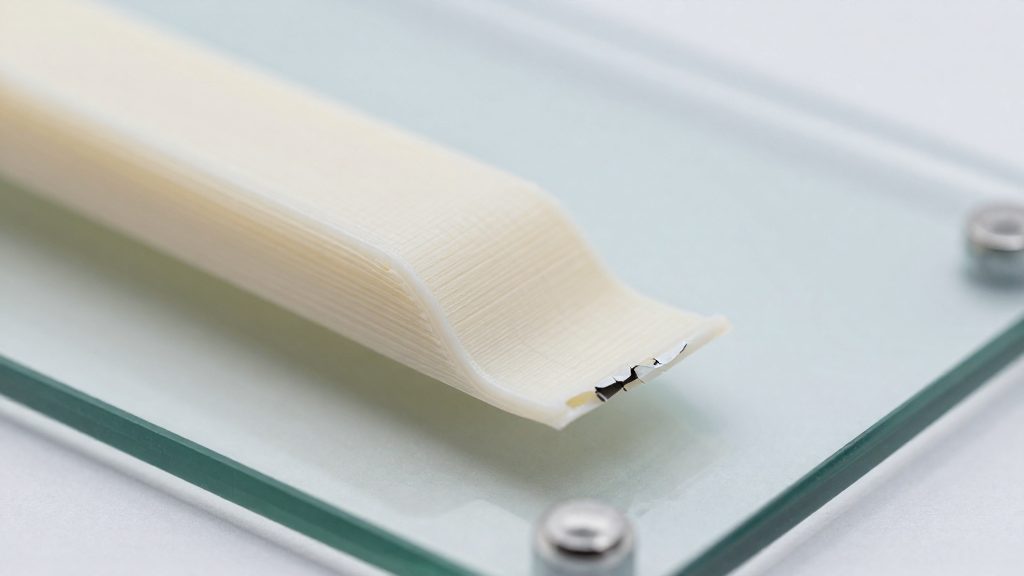
Beyond that angle, the overlap shrinks further. Each new layer is anchored by less material, so the freshly extruded plastic has more room to droop before it solidifies. The sag is cumulative: a small droop on one layer becomes the foundation for the next, so the error grows layer by layer. This is why sagging tends to get worse the steeper the overhang is.
The real limit depends on the specific printer and filament, so the same model can succeed on one machine and sag on another.
How do you orient a model to avoid supports?
Build orientation is the simplest way to reduce supports because you set it before the slicer generates any. Rotating the part changes which surfaces are steep. A face that is a steep overhang in one position can become a gentle slope in another.
Rotate the model and check the slicer preview
Rotate or tilt the model in your slicer and look for downward-facing surfaces that exceed about 45° from the vertical. Try positions that bring those surfaces closer to horizontal. Then check the slicer preview before you add any supports, because it shows which areas would still need them.
| Position | Effect on overhangs |
|---|---|
| Default vertical placement | Steep overhangs remain on the model |
| Laid flat | Anycubic suggests trying this instead of defaulting to vertical |
| Flipped | Can remove the overhangs that required supports in the original position |
Flipping a T-shaped part
A T-shaped part shows the effect clearly. In one orientation it needs supports, but flipped it does not, according to Wevolver (2023). Test both orientations in the preview before you commit to one. Compare how much of the model sits over empty space in each position, and choose the one with fewer unsupported faces.
Cura does not orient parts automatically
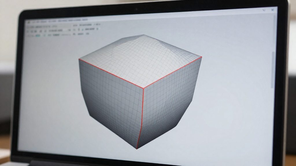
Cura does not automatically orient parts to minimize supports, although third-party plugins exist. Its experimental “make overhang printable” option deforms the model so overhangs stay at a maximum of 45°. It gives little control over the result, so it is best suited to cosmetic parts. For functional parts, manual rotation with a preview check is the more predictable method.
Use chamfers and splits to remove overhangs
When a steep face cannot be reoriented away, the geometry itself can be changed. Two geometric edits can remove such overhangs: replacing right angles with chamfers, and dividing the part into split sections that each print without overhangs.
Replacing right angles with chamfers
A chamfer is an angled bevel that replaces a sharp 90° corner. Wevolver states that chamfers can replace right angles on overhanging features, which brings the surface closer to the 45° limit. The change is made in the CAD model before slicing, so the slicer receives a geometry that needs less or no support material on that edge.
Splitting parts into separately printed sections
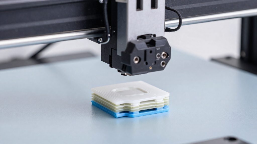
Anycubic (2023-12-13) notes that a model can be split into overhang-free sections, printed separately, and glued together after printing. This avoids the supports that complex parts would otherwise need. Plan the cut lines so that each section’s faces stay within the 45° limit, and place the seams where the glued joint will be least visible on the finished part.
Cura’s experimental overhang option
Apply it to a copy of the model and check the preview to see how much the geometry has changed.
| Approach | Limit stated in the sources | Best use |
|---|---|---|
| Chamfer replacing a right angle | Reduces overhang toward 45° where feasible | Edges that can be redesigned |
| Split into overhang-free sections | Each section stays within the 45° limit | Complex parts that cannot be printed in one piece |
Can bridging replace supports?
A bridge is a horizontal span printed between two points without support material underneath it. According to Wevolver (2023), bridges are horizontal spans between vertical supports that are printed without supports, and shorter bridges sag less and are easier to print. Bridging can therefore replace supports for short gaps, such as a horizontal feature joining two walls or two solid endpoints.
Bridges versus sloped overhangs
A bridge and a sloped overhang fail in different ways because they are anchored differently.
| Feature | Bridge (horizontal span) | Sloped overhang |
|---|---|---|
| Anchoring | Two endpoints, with nothing beneath the span | Each layer rests partly on the layer below |
| Printability | Works without supports when the span is short | Depends on the angle of the surface |
| Typical fix | Shorten the span or reorient the part | Reorient, or add supports |
A sloped overhang keeps some contact with the layer below along its whole length. A bridge has no contact underneath, so the filament must hold its shape across the gap until it reaches the endpoints.
Where bridging breaks down
Bridging fails when the span is too long for the filament to hold its shape, and the resulting sag shows up as drooping or uneven lines underneath the span. Test a short bridge on your own printer and filament to find the longest span that stays clean.
The following method reduces the span or removes the need for a bridge altogether:
- Reorientation: Reorienting a part can remove overhangs entirely. Rotating or tilting the model in the slicer can also turn a steep overhang into a gentler slope.
Cooling and speed settings for steeper overhangs
Part cooling and outer wall speed are two settings that can help an FDM printer hold an overhang steeper than the common 45° baseline from vertical, which is a guideline rather than a hard limit. Strong part cooling lets the filament solidify faster, which allows steeper angles to hold, and many printers can handle 60° or more with good airflow.
Part cooling airflow is the first lever. Anycubic (2023) recommends running the part cooling fan at 100% on overhangs. Because the filament solidifies faster at that setting, the same printer can produce a steeper overhang than it can at lower fan speeds.
Outer wall speed is the second lever. Slowing the outer wall speed on overhangs also helps, according to Snapmaker (2026). Dial in the exact speed on your own printer and filament.
A practical sequence for a steep section:
- Reorient the part first and check the slicer preview, because a gentler slope may remove the need for extra cooling.
- Set the part cooling fan to 100% for the overhang regions.
- Lower the outer wall speed for those same regions.
- Confirm the result on the printed underside before increasing the angle further.
How do you find your printer’s real limit?
Measuring your own setup is more reliable than relying on a general rule. According to Snapmaker (2026-01-09), printing a labeled overhang test model is the fastest way to find the real overhang limit of your printer and filament. A single test print shows where your setup starts to fail.
Printing a labeled overhang test model
Choose a labeled overhang test model, a part with sloped sections that are each marked with their angle. Print it without supports, in its default orientation, using the same slicer profile you use for regular parts. Keeping your normal profile makes the result reflect your actual setup, not a special test configuration.
Identifying the angle where surfaces start failing
Once the print has cooled, inspect the underside of each sloped section, starting with the gentlest angle and moving steeper. Look for drooping, lumpy or rough surfaces, and gaps where the layers no longer bridge the air. The steepest section that still looks clean is your practical limit, and the first section with visible sagging marks where the print fails. Note that angle alongside the filament name, since the result applies only to that material.
Testing separately for each filament type
Each filament can give a different result, so run the test again for every material you print with. A limit measured on one spool does not transfer to another filament type. Repeat the test whenever you switch material, because the result is tied to that filament and your printer together.
Strength trade-offs of orientation
Orientation affects strength as well as supports. According to Wevolver (2023), printed parts are weakest along the Z axis, the direction in which layers are stacked. A change that removes supports can therefore place the weakest direction under load. Each layer bonds to the one below it, and that bond is where a part is most likely to separate.
Layer adhesion along the Z axis
The layer-to-layer bond carries all load across Z. Parts printed flat keep their long, load-bearing features in the XY plane, where the material is continuous within each layer. Parts printed upright may have their long features running vertically, so the bonds between layers must hold them together. Before accepting a new orientation, identify the direction of the main load and confirm it does not pull the layers apart.
Orientation trade-off between supports and strength
Each orientation changes both the support count and the strength profile:
| Orientation | Overhang result | Strength consideration |
|---|---|---|
| Original upright position | Overhangs steeper than 45° need supports | Layers stacked as designed |
| Flipped or laid flat | Overhangs can be removed entirely | Load may now run across layers |
| Split into overhang-free sections (Anycubic, 2023) | Each section prints without supports | Glued joints become the weak point |
Strength loss at split joints and seams
Each glued seam is a surface bonded by adhesive rather than by continuous printed layers, so it is the most likely failure point in the assembled part. Place seams in areas that see the least load, and orient the glued faces so that the expected force does not pull them apart.