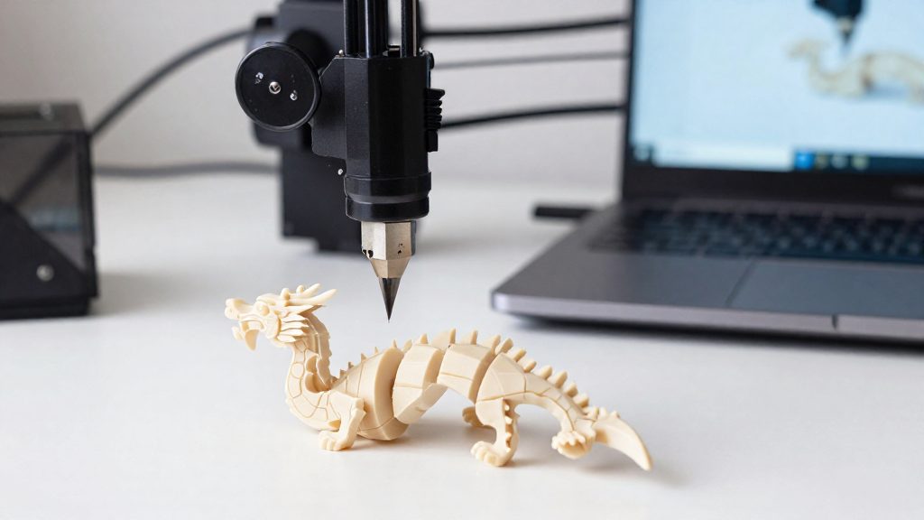
A large STL model needs splitting when at least one of its dimensions exceeds the build volume, the maximum X, Y and Z space the printer can reach. A part that does not fit cannot be printed in one piece, so cutting it into sections lets each piece print within the limit. The same cut can also improve print quality. Check your machine’s specification for its build volume before cutting.
Why split a large STL model?
Build volume limits
A model must be split when its bounding box is larger than the printer’s build volume in any direction. Only the sections that fit inside that volume can print at once. For resin printing, ChiTuBox and Lychee Slicer include built-in split functions, so the cut can be made inside the slicer instead of in a separate program.
Print quality and material waste
Splitting a model can improve print quality and reduce material waste, as SelfCAD notes for its Cut With Plane tool. In SelfCAD, enable Split Objects and Fill Cuts before exporting the pieces. Before cutting, compare the model’s dimensions with the build volume of your printer, so you split only the parts that cannot fit.
Multi-color and multi-material printing
Splitting also makes multi-color or multi-material printing possible, because each section can be printed separately in its own material or color. The pieces are then joined after printing. This approach works for both FDM and resin printers, and the same split that solves a size problem can separate color zones within one model.

Where should you cut the model?
The cut plane determines how visible the seam is, how strong the joint becomes, and whether fine detail survives the split. Choose the location before you start splitting, because the same model can be cut cleanly or badly depending on where the plane passes.
Place cuts on flat, low-detail surfaces
Look for flat, low-detail surfaces: the flat base of a figure, the side panel of a box-shaped housing, or a large smooth face. A planar cut that meets a planar face lets the two halves mate over a broad area, which gives the glue more contact.
- Avoid curved or sculpted areas, where the mating faces are irregular and harder to align.
- Place the seam where it will be hidden or seen least once the parts are assembled.
Keep cuts away from thin walls and fine features
Thin walls are the weakest part of most prints. A cut through a thin section leaves very little material to glue, and the part is more likely to break during handling and sanding. The same applies to text, grilles, small holes and sharp edges, which a cut can distort or fill.
Choose a joint shape that resists separation
A joint shape that interlocks resists pulling apart better than a plain flat butt joint, which depends almost entirely on the adhesive. Keep the joint faces clean and free of large gaps so the glue can bond along the full contact area.
Free tools that can split STL files
Four tools cover most cases where an STL is too large for a home printer’s build volume. Two are general-purpose: 3D Builder, a Windows app, and Cura Mesh Tools, a plugin for the Cura slicer. The other two, ChiTuBox and Lychee Slicer, are resin-printing programs with split functions built in.
| Tool | Type | Availability |
|---|---|---|
| 3D Builder | Windows application | Free, preloaded on many Windows PCs |
| Cura Mesh Tools | Plugin | Works inside the Cura slicer |
| ChiTuBox | Resin slicer | Built-in split function |
| Lychee Slicer | Resin slicer | Built-in split function |
According to 3Dprinterly (2026), 3D Builder is free and preloaded on many Windows PCs, so it is often the quickest option for Windows users because no separate download is needed. The Cura Mesh Tools plugin keeps the work in one place: you split the model and then slice the resulting pieces without leaving the application.
For resin printing, resin split functions in ChiTuBox and Lychee Slicer let you divide the model in the same program that prepares the file for the printer. This avoids exporting an intermediate file and reimporting it.
Whichever tool you use, confirm that every piece fits your printer’s build volume before slicing.
How to split an STL in Meshmixer or Blender
Meshmixer and Blender can both cut a model into pieces that fit your build volume, but they finish the job differently. Meshmixer produces separate shells that you export one at a time, while Blender leaves the cut open, so you have to close it yourself. An oversized STL can also be split in CAD software such as Fusion 360. The steps below cover the two tools named in this section.
Cutting and exporting in Meshmixer
Open the model in Meshmixer, go to Edit, then choose Plane Cut. Place the cutting plane where you want the seam. Set the cut type to slice so that both halves are kept. If you choose a cut type that discards one side, you lose part of the model, which defeats the purpose of splitting it.
Once the cut is made, use Separate Shells to divide the result into individual bodies. Each half now exists as its own shell, so you can select and export it independently. Export each part as a separate STL file and repeat the process for every piece. Keep the file names tied to the part position, such as “top” and “base”, so you can match the pieces later when you assemble them.
Cutting and closing a model in Blender
In Blender, the cut is made with the Bisect tool in Edit Mode, which slices the mesh along a plane you define. The cut can leave the surface open, depending on how the cut is made. According to 3Dprinterly (2026), a split can leave an open gap in the mesh, which makes the part non-manifold and can cause slicing errors.
To close the gap, stay in Edit Mode and loop-select the cut edge, which is the boundary ring left by the cut. With the loop selected, press F. This fills the opening with a face so that the part stays closed. Check the part for remaining open edges before you export it as STL.
| Tool | Cut step | Step after the cut |
|---|---|---|
| Meshmixer | Edit > Plane Cut, cut type set to slice | Separate Shells, then export each part |
| Blender | Bisect tool in Edit Mode | Loop-select the cut edge, press F to fill |

How do you keep the parts aligned?
Once a model is cut, the two halves have no built-in reference, so they can slide or rotate during assembly. Alignment pins solve this by giving one piece a peg and the other a matching hole. According to 3Dprinterly (2026), Meshmixer can also add alignment pins to help line up the pieces after a split.
The usual sequence in Meshmixer is:
- Split the model with Edit > Plane Cut, with the cut type set to slice so both halves are kept.
- Add alignment pins with Meshmixer’s pin feature if you want help lining up the pieces, then check them in the model before export.
- Separate the shells.
Pins should sit in the cut face, spaced so that neither piece can rotate once they are joined. Keep the peg and hole clearances consistent across all joints so that every pair fits the same way, and check that the two halves of each pin pair belong to the same joint.
Dry-fitting before bonding
Dry-fitting means assembling the printed pieces without adhesive. Do this before any bonding step. Check three things:
- The joint closes flush along the whole cut face.
- Each pin seats fully in its hole.
- The assembled part does not rock or twist.
If a pin binds or a joint gaps, adjust the registration feature in the model and reprint only the affected piece. Forcing a misfit into place with adhesive leaves the error permanent.
Orienting and arranging each part on the build plate
Once a model is split, each piece is a separate object in the slicer, so you can position each one on its own. A single oversized model has one orientation for the whole print, but separate pieces can each be rotated to suit their shape. According to 3Dprinterly (2026), reorienting split pieces can help them use the full build plate area. This is often the practical gain: a part too large to fit in one orientation may fit once it is laid down or turned.
Reorienting each piece to use the plate
Load all the pieces into the slicer and rotate each one individually rather than keeping the original upright position.
- Rotate each piece separately so its footprint covers more of the plate.
- Recheck the height after each rotation, because laying a part down changes which dimension is the tallest.
- Repeat for every piece. The best orientation for one part may not suit its neighbours.
Arranging several parts on one plate
When each piece is oriented, place several of them on the same build plate to print in one run. Most slicers offer an auto-arrange function that packs objects onto the bed, and you can drag pieces manually if you want a specific layout. Leave space between parts so that no piece sits against the edge of the build area.
Choosing orientation for each part separately
Because each piece prints independently, its orientation does not have to match the others. A piece with a large flat face can be placed with that face on the bed, while a piece with fine detail can be positioned to protect that detail.
Gluing and finishing the parts
Once the pieces are printed, the workflow is to sand them and then join them with cyanoacrylate adhesive, the chemical family that includes ordinary superglue. According to 3Dprinterly (2026), split parts are sanded before they are joined with superglue. Both steps matter because the mating faces of an FDM print still carry layer lines, and the glue can only bond the surfaces it actually touches.
Sanding the part surfaces
Sand the faces that will meet the neighbouring piece so they are flat and no longer show the print texture. Work on each part separately and check that the cut faces sit flush against each other. Remove the sanding dust with a dry brush or a cloth before applying adhesive, because loose particles on the surface weaken the bond.
Joining the parts with superglue
Work in a ventilated area and wear eye protection and gloves, because cyanoacrylate bonds skin instantly. Apply a thin layer of cyanoacrylate to one of the sanded faces, then press the two parts together. Cyanoacrylate sets quickly, so hold the pieces in position until the joint has cured enough to stay put, and avoid moving the parts while the glue is still setting. Use only a small amount: excess glue spreads into the seam and makes the later finishing harder.
Finishing and smoothing the seam
After bonding, sand the seam to remove any adhesive that squeezed out and to bring the joint level with the surrounding surface. Work gently across the seam rather than concentrating on one spot, so you do not create a dip beside the joint. The result is a seam that is much less visible on the finished model, though some line will usually remain on the surface.
Frequently asked questions
Which free software can split an oversized STL without CAD experience?
3D Builder is free and preloaded on many Windows PCs, so it is a simple option for cutting a model. Cura’s Mesh Tools plugin and CAD programs such as Fusion 360 also include split functions.
How do you join the printed pieces so the seam holds?
Sand the printed parts, then bond them with superglue. Some tools, such as Meshmixer, can also add alignment pins to help line up the halves before gluing.
Why does my Blender split show an open gap in the mesh?
A split can leave the mesh open, so the part is no longer closed. Loop-select the cut edge and press F to fill the gap. This does not happen with every split, so check the mesh before exporting.