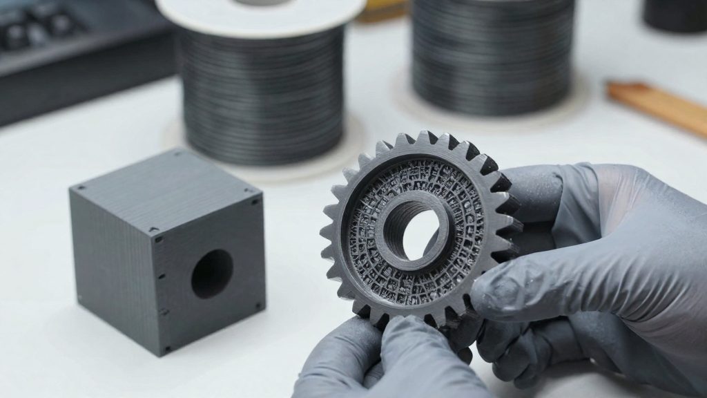
Prusa Research reports that 10–20% infill gave a useful balance of strength, print reliability, printing time and material consumption in its testing. That makes this range a sensible starting point for most functional parts. It is general guidance, not a validated setting for every part, so load-bearing prints may need a different value.
What Infill Percentage Makes Functional Parts Strong?
Infill is the internal material between a part’s perimeters. Beyond internal strength, Prusa notes that infill supports the top layers, which would otherwise have to bridge empty space, so density also affects surface quality.
Density is a trade-off between four factors:
- Strength: More infill adds material inside the part, but no opened source establishes a universal percentage increase in strength when density is doubled.
- Print time: Higher density lengthens the print.
- Material consumption: Higher density uses more filament.
- Reliability: Prusa’s 10–20% range was identified as the balance point across these factors.
Recommendations differ by application:
| Source | Recommended infill | Application and condition |
|---|---|---|
| Prusa Research (2021) | 10–20% | General balanced starting point for functional parts |
| Prusa Research, general documentation | Above 30% rarely needed | General guidance |
| FIRST robotics guidance | 40–60% | Load-bearing PLA parts, with four alternating five walls |
| FIRST robotics guidance | 80–100% | Structural PLA robot parts exposed to drop shocks |
These figures do not establish a universal threshold. A value of 20–30% is not established as sufficient for all strong functional parts.
To find the right value for a specific part, print sample models at different densities and compare the results, as Prusa recommends when adjusting infill settings.
Choose Infill Density for the Load
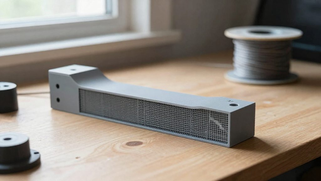
Infill density matters most for compression resistance and stiffness. Prusa notes that increasing infill can raise both stiffness and compression resistance, and it singles out infill as particularly useful for compression, while perimeter count is its main lever for strengthening prints in other directions. Raising the percentage is therefore a direct way to adapt a part to the force it will carry, but the right value depends on the load, not on a single universal number.
Match Density to the Dominant Load
Start by identifying the load the part sees most often:
- Compression (a part that is squeezed or stacked under weight): raise the infill percentage, since infill is what resists this load.
- Bending or impact (a bracket, clip or housing hit by shocks): combine higher infill with enough perimeters, because the walls carry much of this load.
- Light or decorative loads: standard infill is usually enough, which keeps print time and material use down.
Known Density Ranges
Recommendations differ by application, so treat these figures as starting points rather than thresholds:
| Source | Application | Recommended infill |
|---|---|---|
| Prusa Research (2021-01-22) | General testing, balance of strength, reliability, time and material | 10–20% |
| Prusa Research | General documentation, most parts | Above 30% rarely needed |
| FIRST robotics guidance | Load-bearing PLA parts, four alternating five walls | 40–60% |
| FIRST robotics guidance | Structural PLA parts exposed to drop shocks | 80–100%, with a 90% maximum to allow for overextrusion |
The 10–20% range is general guidance, not a validated setting for every functional part. The FIRST figures apply to robot parts, not to all functional prints.
Stiffness Gains Are Not Linear
No opened source establishes a universal strength increase when infill density is doubled. Increase the percentage in steps and check the result on the actual part, rather than assuming that 40% is twice as strong as 20%.
Should You Add Walls Before Infill?
Yes. Prusa Research recommends increasing the perimeter count to strengthen a print. Perimeters are the outer walls that each layer is built from, so this setting changes the part’s outer shell rather than its interior fill. For a functional part that needs more strength, adjusting walls is a logical first step before you raise infill density.
Published guidance does not give a measured strength gain per added perimeter, so the effect has to be confirmed on your own prints. To test it:
- In your slicer, raise the perimeter count and leave infill density unchanged.
- Print a sample model with the new setting.
- Compare it with the previous print, then change infill only if the result still falls short.
Prusa Research also recommends printing sample models and comparing results when adjusting infill settings, so the same check applies here.
Gyroid, Grid, and Rectilinear: Strength and Printing Behavior
Infill pattern changes how the same density is distributed inside a part, so two settings at 20% can behave differently.
- Gyroid is described by Prusa as a three-dimensional infill with a good strength-to-weight ratio. Within a single layer it has no self-intersections, so the extruded path never crosses itself at that height.
- Grid crosses itself within each layer. The material that accumulates at those crossings can cause nozzle collisions or print failure, which makes grid a higher-risk choice for parts that must print reliably.
- Rectilinear is the pattern PrusaSlicer switches to automatically at 100% density, and Prusa recommends it for solid infill. Its use at full density is covered in the section on 100% infill.
Strength Versus Weight
To choose a pattern, start from the load the part must carry. Use gyroid when you want a good strength-to-weight ratio without the crossing problem that grid introduces.
When Does Higher Infill Make Sense?
Raising infill density can improve support beneath closed top surfaces and can increase stiffness and compression resistance. According to Prusa Research, infill supports the top layers, which would otherwise have to bridge empty space, so interior density directly affects how the surface prints.
Top layers bridging empty space
With sparse infill, the first solid layers above the interior are laid across open cells. Each higher-density infill pattern gives those layers more material to rest on, which shortens the unsupported spans. Parts with large flat top faces, or faces that must hold a load or stay closed, are the cases where this matters most.
Surface quality effects of raising infill density
Infill density affects the appearance of the top surface as well as its structure. Prusa Research notes this link in its slicer documentation. Its general documentation also states that infill above 30% is rarely needed, but this is general guidance, not a threshold for every top surface.
To find the right density for a specific top surface, print sample models at two or three infill values and compare the finished tops before changing the setting for the full part.
Is 100% Infill Worth It?
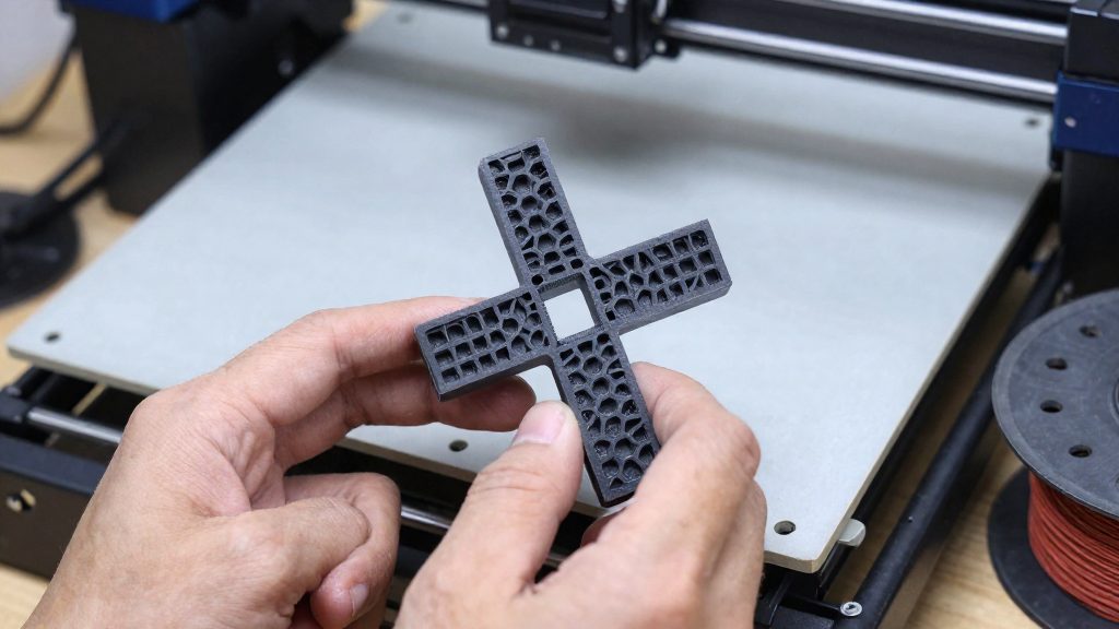
Fully solid infill is rarely the most efficient route to a strong part, and the sources in this fact set do not establish that 100% infill is needed for functional parts in general. Prusa’s own testing found that 10–20% infill gave a useful balance of strength, print reliability, printing time and material consumption, although Prusa presents this as general guidance rather than a validated setting for every functional part (Prusa Research, 2021-01-22). The real question is therefore whether the extra material and time of a solid interior earns a measurable gain for your specific load.
What PrusaSlicer does at 100%
Setting infill density to 100% has a side effect in PrusaSlicer: the slicer automatically switches to the rectilinear pattern. Prusa recommends this pattern for solid infill, so you do not need to change it manually when you go fully solid (Prusa Research).
Trade-offs of solid infill against sparse infill
- Stiffness and compression: Increasing infill can raise stiffness and compression resistance, according to Prusa’s slicer documentation (Prusa Research). Prusa also identifies infill as particularly useful for compression resistance.
- Surface quality: Infill supports the top layers, which would otherwise have to bridge empty space. Denser infill therefore also affects how smooth the visible surface looks.
- Material and time: Every step up in density adds filament and print time, which is the cost side that Prusa’s 10–20% guidance is built around.
- Strength gain per percent: No opened source establishes a universal percentage increase in strength when infill density is doubled, so the benefit of going from 40% to 80% cannot be quantified from these sources.
Higher-density recommendations exist for specific applications. FIRST’s robotics guidance, a US-based competition body, recommends 40–60% for load-bearing PLA parts with four alternating five walls, and lists 80–100% for structural PLA robot parts exposed to drop shocks, while capping the value at 90% to allow for overextrusion (FIRST, ftc-docs.firstinspires.org). These figures come from one competition context and do not establish a threshold for all functional parts. The sources also do not establish resin-printing equivalents for these filament-slicer recommendations.
Test Settings Before Printing the Final Part
Print sample prints with the infill settings you are considering before you commit to the full functional part. Prusa recommends printing sample models and comparing the results whenever you adjust infill settings (Prusa Research, 2021-01-22). A sample shows how a setting behaves on your own printer and material.
What to Compare Across Samples
Compare stiffness, compression resistance and top surface quality across infill samples, and evaluate perimeter count in a separate test series.
- Stiffness and compression resistance: Increasing infill can increase both, according to Prusa’s slicer documentation. Compare the samples under the type of load the part will face.
- Top surface quality: Infill supports the top layers that would otherwise bridge empty space. Inspect the top surface of each sample, because the infill setting affects the result.
- Perimeter count: Prusa recommends increasing perimeters to strengthen a print. Test perimeter count separately: hold infill density and pattern constant while changing walls, then hold perimeter count constant while changing infill.
Comparing Infill Patterns
The pattern affects both strength and print reliability, so include it in the sample set:
| Pattern | Documented trait | What to check on the sample |
|---|---|---|
| Gyroid | Three-dimensional, good strength-to-weight ratio, no self-intersections within a single layer | Compare weight and stiffness against other patterns at the same density |
| Grid | Crosses itself within each layer; accumulated material at the crossings can cause nozzle collisions or print failure | Inspect the crossings for accumulated material and check that the print completed |
Print the samples at the same size and orientation as the final part, so the comparison reflects only the infill setting.